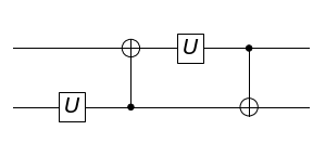
A note about implementing a controlled version of [U(0), CNOT(0, 1), U(1), CNOT(1, 0)] using only 2-qubit gates.
Contents
- Introduction
- Controlled-$U$ gates
- Initial Approach using Toffoli Gate
- A 2-qubit version of Toffoli
- Alternative Circuit without Toffoli
- CNOT and Hadamard Transform Property
- A 2-qubit Controlled-$V$ Circuit
- Alternate Controlled-$H$ Construction
- Additional notes
Introduction
The one-clean-qubit model lets you estimate the normalised trace $\mathrm{Tr}(U)/\mathrm{Tr}(I)$ of an $n$-qubit gate $U$ which is a task for which no known classical poly-time algorithm exists according to this problem description from MIT 8.371.2x: Quantum Information Science II, Part 2 from the MIT Open Learning Library.
This can be achieved using a circuit of the form

which can be expressed as [H(0), CU(0, 1), H(0)]
It can easily be shown that the approach works for arbitrary values of $n$. The assignment problem asks you to implement the circuit for a 2 qubit gate V = [U(0), CNOT(0, 1), U(1), CNOT(1, 0)]

Note that:
- Numbering for qubits increases from bottom to top.
- The gates are applied from left to right
- For example in matrix form
[X(0), Y(1), Z(0)]would beZ(0) x Y(1) x X(0)
Controlled-$U$ gates
Assuming that bit 0 is the control bit, any controlled-U (CU) gate has the form
\[\begin{bmatrix} I & 0 \\ 0 & U \end{bmatrix}\]Suppose $U = U_1 \cdot U_2\cdot \ldots \cdot U_n$, then the gate can also be implemented as a sequence of gates
\[\begin{bmatrix} I & 0 \\ 0 & U_1 \end{bmatrix} \times \begin{bmatrix} I & 0 \\ 0 & U_2 \end{bmatrix} \times \cdots \times \begin{bmatrix} I & 0 \\ 0 & U_n \end{bmatrix}\]For the gate V in this problem we have V = CNOT(2, 1) x U(2) x CNOT(1, 2) x U(1) (since gates are applied from left to right in the list, matrix multiplication goes right to left), where U is an arbitrary unitary matrix.
The question required you to give the circuit to estimate the trace for V, assuming you had access to controlled-U CU. The key aspect was to implement controlled-V.
Initial Approach using Toffoli Gate
It would seem you can quite straightforwardly construct
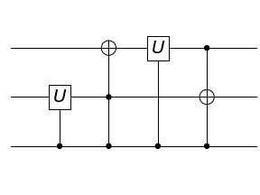
CV = [CU(0,1), Toffoli(0, 1, 2), CU(0, 2), Toffoli(0, 2, 1)]

where Toffoli is the controlled CNOT gate, a 3-qubit gate which causes CNOT to be applied only if the qubit 0 is 1.
\[\text{CNOT} = \begin{bmatrix} 1 & 0 & 0 & 0 \\ 0 & 1 & 0 & 0 \\ 0 & 0 & 0 & 1 \\ 0 & 0 & 1 & 0 \end{bmatrix} = \begin{bmatrix} I & 0 \\ 0 & \text{X}\end{bmatrix}\] \[\text{Toffoli}=\begin{bmatrix} 1 & 0 & 0 & 0 & 0 & 0 & 0 & 0 \\ 0 & 1 & 0 & 0 & 0 & 0 & 0 & 0 \\ 0 & 0 & 1 & 0 & 0 & 0 & 0 & 0 \\ 0 & 0 & 0 & 1 & 0 & 0 & 0 & 0 \\ 0 & 0 & 0 & 0 & 1 & 0 & 0 & 0 \\ 0 & 0 & 0 & 0 & 0 & 1 & 0 & 0 \\ 0 & 0 & 0 & 0 & 0 & 0 & 0 & 1 \\ 0 & 0 & 0 & 0 & 0 & 0 & 1 & 0 \end{bmatrix} = \begin{bmatrix} I & 0 \\ 0 & \text{CNOT}\end{bmatrix}\]The problem arose when the grader seemed not to accept the Toffoli gate. Initially I tried a number of variations TOFFOLI, TOFF, CCX, CCNOT, toffoli. I finally discovered that the accepted value was Toffoli! But before that, I assumed that it must be the case that this particular gate was realisable using only 2-qubit gates and that this is what the answer expected so I spent some time trying construct controlled-V in this fashion.
A 2-qubit version of Toffoli
I learned that it is possible to construct Toffoli as well as other 3-qubit gates with 2 control qubits using only 2-qubit gates. The following is a circuit for Toffoli gate using 6 CNOT gates and a number of single qubit gates.

Source: Wikipedia, created by Geek3 (CC BY-SA 4.0)
However when I input this sequence in place of Toffoli, the grader failed to return a response of correct or not. It might have been a timeout in the backend maybe because of the large number of gates involved. It returned the following error
Couldn't execute jailed code: stdout: b'', stderr: b'' with status code: -24
It is suggested here that a timeout might possibly be the reason.
This got me thinking whether the overall V could be realised without having to rely on a Toffoli gate. Turns out that it can.
Alternative Circuit without Toffoli
I first thought about what happens when you simply substitute U with CU. The resulting circuit is
[CU(0, 1), CNOT(1, 2), CU(0, 2), CNOT(2, 1)]
When qubit 0 is 1, the result is [U(1), CNOT(1, 2), U(2), CNOT(2, 1)] = V but when qubit 0 is 0, it is [CNOT(1, 2), CNOT(2, 1)] which is not the identity.
Now CNOT(x, y) is its own inverse and there are two CNOT gates in this circuit but as it stands they don’t cancel since the control and target qubits are different in each case. But what if you could make it so that when qubit 0 is 0, CNOT(1, 2) is applied both times?
CNOT and Hadamard Transform Property
CNOT has a special property that when you apply a Hadamard transform to the inputs and outputs of CNOT(x, y), the result is CNOT(y, x) i.e. the control and target qubits are flipped

Source: Wikipedia, created by DavidBoden (CC BY-SA 3.0)
The ability to flip CNOT using only single qubit gates is key to the solution. Because as we have seen, it suffices to control the order of qubits input to the CNOT gate and not whether the CNOT gate is applied.
Now assume we have access to controlled-Hadamard gates (as was the case in the assignment but see below for how you can construct one using Pauli matrices and rotations). If we construct the second CNOT gate CNOT(2,1) using CNOT(1,2) and the controlled versions of H, then CNOT(1, 2) will only get flipped when qubit 0 is 1. Therefore when qubit 0 is 0 it will invert the other CNOT(1, 2).
A 2-qubit Controlled-$V$ Circuit
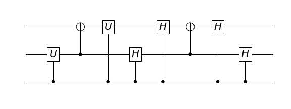
The circuit for controlled-V is as follows:
CV = [CU(0, 1), CNOT(1, 2), CU(0, 2),
      CH(0, 1), CH(0, 2), CNOT(1, 2), CH(0, 2), CH(0, 1)]

Sadly the grader kept failing for this circuit as well i.e. returning the same error as before and not responding with correct or incorrect.
However we can verify that the circuit is indeed equivalent to controlled-V. When qubit 0 is 1, the gates controlled by qubit 0 are applied so that qubits 1 and 2 are transformed as
[U(1), CNOT(1, 2), U(2), H(1), H(2), CNOT(1, 2), H(2), H(1)]
 = [U(1), CNOT(1, 2), U(2), CNOT(2, 1)] = V
and when qubit 0 is 0, only the gates not controlled by qubit 0 are applied so qubits 1 and 2 are transformed as
[CNOT(1, 2), CNOT(1, 2)] = I
Since the circuit applies V when qubit 0 is 1 and identity when qubit 0 is 0, it satisfies the definition of controlled-V.
A notebook that verifies the circuit for controlled-V using matrices can be found here.
To use this for trace estimation you simply need to apply a Hadamard transform to qubit 0 at the input and output as follows
[H(0), CU(0, 1), CNOT(1, 2), CU(0, 2),
      CH(0, 1), CH(0, 2), CNOT(1, 2), CH(0, 2), CH(0, 1), H(0)]

Alternate Controlled-$H$ Construction
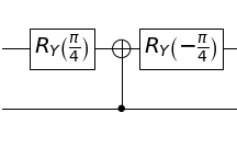
You can construct CH using a combination of a CNOT and rotations since
This follows from the fact that
\[R_Y(\alpha) = \exp\left(-i\frac{\alpha}{2}Y\right) = I\cos\left(\frac{\alpha}{2}\right) - iY\sin\left(\frac{\alpha}{2}\right)\]You can construct the circuit as

When qubit 0 is 1, the output is $R_Y\left(-\frac{\pi}{4}\right) \cdot X \cdot R_Y\left(\frac{\pi}{4}\right) = H$ and when qubit 0 is 0, the output is $R_Y\left(-\frac{\pi}{4}\right) \cdot R_Y\left(\frac{\pi}{4}\right) = I$, as required.
Additional notes
Just for fun I have been thinking about how the circuit above could be generalised. Here I will note down my ideas as I think of them.
Sequence of 2-qubit qubit 0 controlled gates between Toffoli gates
You can implement any arbitrary sequence of 2-qubit gates $CU_1, \cdots, CU_n$, all controlled by qubit 0, sandwiched between a pair of Toffoli gates with the second control and the target swapped between the two and the Toffoli gates entirely using 2-qubit gates by replacing the Toffoli gates using two CNOT gates where the swapping of the order of control and target in one of the gates is controlled by CH gates as above i.e.
[Toffoli(0, 1, 2), CU_1(0, idx_1),...,CU_n(0, idx_n), Toffoli(0, 2, 1)]
-> [CNOT(1, 2), CU_1(0, idx_1),...,CU_n(0, idx_n), CH(0, 1), CH(0, 2), CNOT(1, 2), CH(0, 2), CH(0, 1)]
where idx_i in [1, 2].
It works because:
- When qubit 0 has the value of 1 in the original configuration, the first Toffoli will function as a CNOT on qubits 1 and 2, the intermediate gates will function as $U_1, \cdots, U_n$, and the second Toffoli gate will also function as a CNOT on qubits 1 and 2 but with control and target flipped; which is exactly what happens in the modified circuit:
[CNOT(1, 2), U_1(0, idx_1),...,U_n(0, idx_n), CNOT(2, 1)]
- When qubit 0 has the value of 0, in the original configuration none of the gates will function so the input will be unchanged whilst in the modified circuit the intermediate controlled gates will not function so the circuit will consist of two CNOT gates where the second CNOT gate will not have its control and target flipped and thus it will be identical to the first CNOT gate, inverting it and leading to an overall identity transform:
[CNOT(1, 2), CNOT(1, 2)] = identity